Getting started with BeeltleboxCI and Vivado: Simple Multiplexer
This is a tutorial designed to show to get started using BeetleboxCI and Vivado, in which we will cover the following:
- Design - Setting up a Vivado project and make a multiplexer in VHLD
- Simulate - Simulating this in Vivado by setting up a test bench
- BeetleboxCI Integratation - Integrating our multiplexer and testbench with BeetleboxCI
- Review - To finish we will compare the simulation results
The tutorial is designed not to be board specific. The accompanying git repository for this tutorial may be found here.
Overview

Multiplexers are one of the most fundamental devices in digital design and are found in a large amount of different applications. Its simplistic design and near ubiquity makes it a great example for getting started with BeetleboxCI. A multiplexer selects one of several different input signalsi0-3 and uses that input as its outputbitout. The selection is based on a seperate input known as select or sel. Multiplexers may be represented as a logic table:
| Sel1 | Sel0 | Output |
|---|---|---|
| 0 | 0 | i0 |
| 0 | 1 | i1 |
| 1 | 0 | i2 |
| 1 | 1 | i3 |
In this tutorial, we will show how to get started with BeetleboxCI through designing a simple multiplexer. We will be focused on simulating it through running Vivado on BeetleboxCI. This tutorial is intended to show the strengths of CI even on a relativly simple design and we will demonstrate how we can iterate both the design and the test.
Tools we are using
- Vivado: Vivado is Xilinx's synthesis and analysis tool for creating bitstreams to be placed onto our FPGA devices. Traditionally this has been centered around the use of HDL languages such as VHDL and Verilog, but the software also includes advanced features for system on chip development, design flow mangement and high level synthesis. Vivado may be installed as part of the Vitis (SW Developer) from Xilinx's website, which may be found here.
- BeetleboxCI: BeetleboxCI is the Continuous Integration software specifically designed for FPGA design.
- Github: Github is a git repository service that can be connected to BeetleboxCI to create an automated workflow.
Tested Environment
- OS: Ubuntu 18.04
- Vivado version: Vivado 2020.1
- FPGA used: Zynq Ultrascale+ series ZCU104
Installation Guide:
- A Github is required to use BeetleboxCI.
- Vivado may be installed as part of the Vitis (SW Developer) from Xilinx's website, which may be found here.
- A BeetleboxCI account. Access may be requested from here.
Design
To create our multiplexer, we will be writing the design file in VHDL.
- Create a directory called workspace in the Vivado folder and change it to be the current working directory. Then we may launch Vivado. The following script assumes that Vivado was installed in the default directory. If it was not, then use the correct installation directory.
# Make workspace
cd /tools/Xilinx/Vivado/2020.1
mkdir workspace
cd /tools/Xilinx/Vivado/2020.1/workspace
source /tools/Xilinx/Vivado/2020.1/settings64.sh
vivado
Create a new project
- Go to
File->Project->New - Name the project
project_ci_sim, keep the same project location. In the next screen choseRTL projectand click through until arriving at theDefault Partscreen. - Select
Boardsand then search for theZCU104 Evaluation Board - Click finish
- Go to
Add VHDL file.
- To add our VHDL file, click the
+button in theSourcestab. - In the
Add or Create Design Sourcestab, clickCreate Fileand name itmultiplexer4_1. Make sure it theVHDLFile Type. - Click
OKon the pop ups.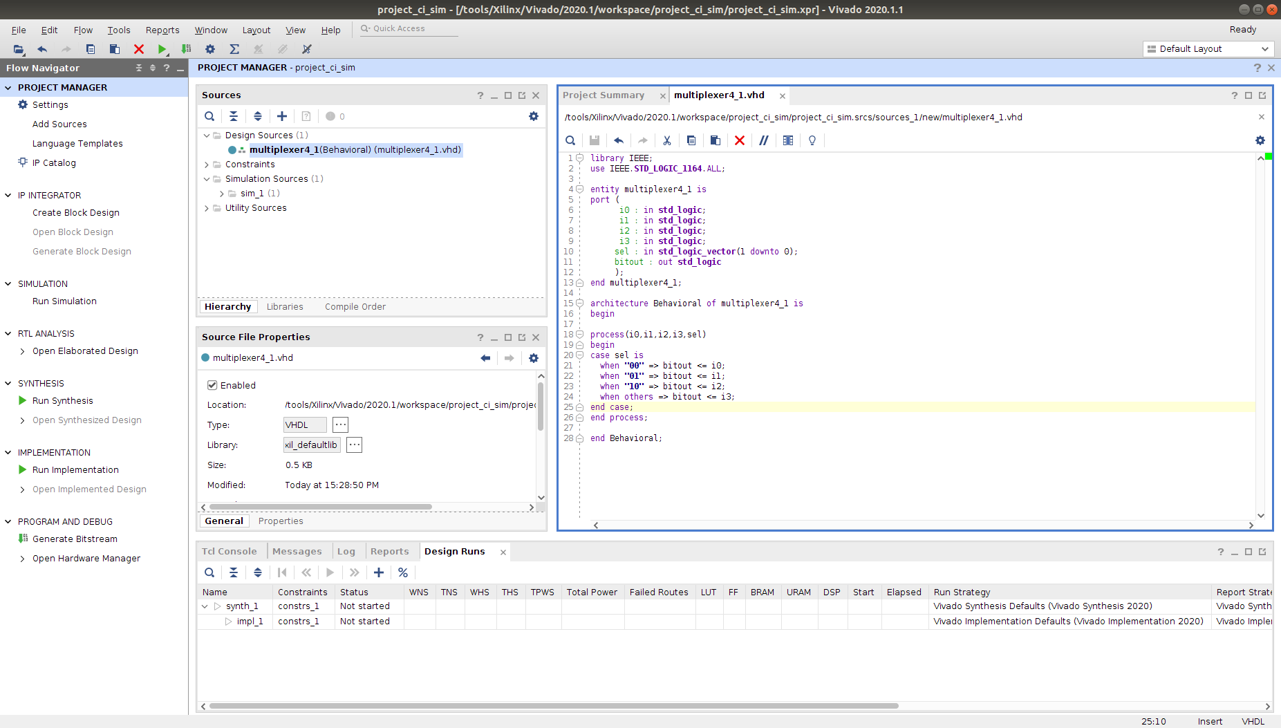
- To add our VHDL file, click the
Double click
multiplexer4_1in the Design Sources tab and copy in the following code:
library IEEE;
use IEEE.STD_LOGIC_1164.ALL;

entity multiplexer4_1 is
port (
      i0 : in std_logic;
      i1 : in std_logic;
      i2 : in std_logic;
      i3 : in std_logic;
     sel : in std_logic_vector(1 downto 0);
     bitout : out std_logic
     );
end multiplexer4_1;

architecture Behavioral of multiplexer4_1 is
begin

process(i0,i1,i2,i3,sel)
begin
case sel is
  when "00" => bitout <= i0;
  when "01" => bitout <= i1;
  when "10" => bitout <= i2;
  when others => bitout <= i3;
end case;
end process;

end Behavioral;
Our multiplexer has four input lines i0-i4, an input selection line sel and an output bitout. To implement the logic, we use a simple case statement to go through the possible values of sel. In each case, we assign a different input i0-i4, to the output bitout, creating our multiplexer.
Simulate
 5. Now we have created our design, we will perform a simulation locally to ensure the correct behaviour before uploading to our Git Repository.
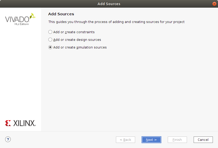
- In the
Sourcestab, right clickSimulation Sources, then clickAdd Sources.... - In the
Add Sourcestab, clickAdd or create simulation sources. - In the next window, click
Create Fileand call ittestbench, ensuring it is also a VHDL file. Then finish creating the file - In the
Sourcestab, double clicktestbenchthen add the following code:
LIBRARY ieee;
USE ieee.std_logic_1164.ALL;

ENTITY testbench IS
END testbench;

ARCHITECTURE behavior OF testbench IS
        SIGNAL i0,i1,i2,i3,bitout :  std_logic:='0';
        SIGNAL sel :  std_logic_vector(1 downto 0):="00";
BEGIN
  UUT : entity work.multiplexer4_1 port map(i0,i1,i2,i3,sel,bitout);

    tb : PROCESS
    BEGIN
          i0<='1';
          i1<='0';
          i2<='1';
          i3<='0';
          sel <="00";
          wait for 2 ns;
          sel <="01";
          wait for 2 ns;
          sel <="10";
            wait for 2 ns;
            sel <="11";
            wait for 2 ns;
          --more input combinations can be given here.
    END PROCESS tb;

END;
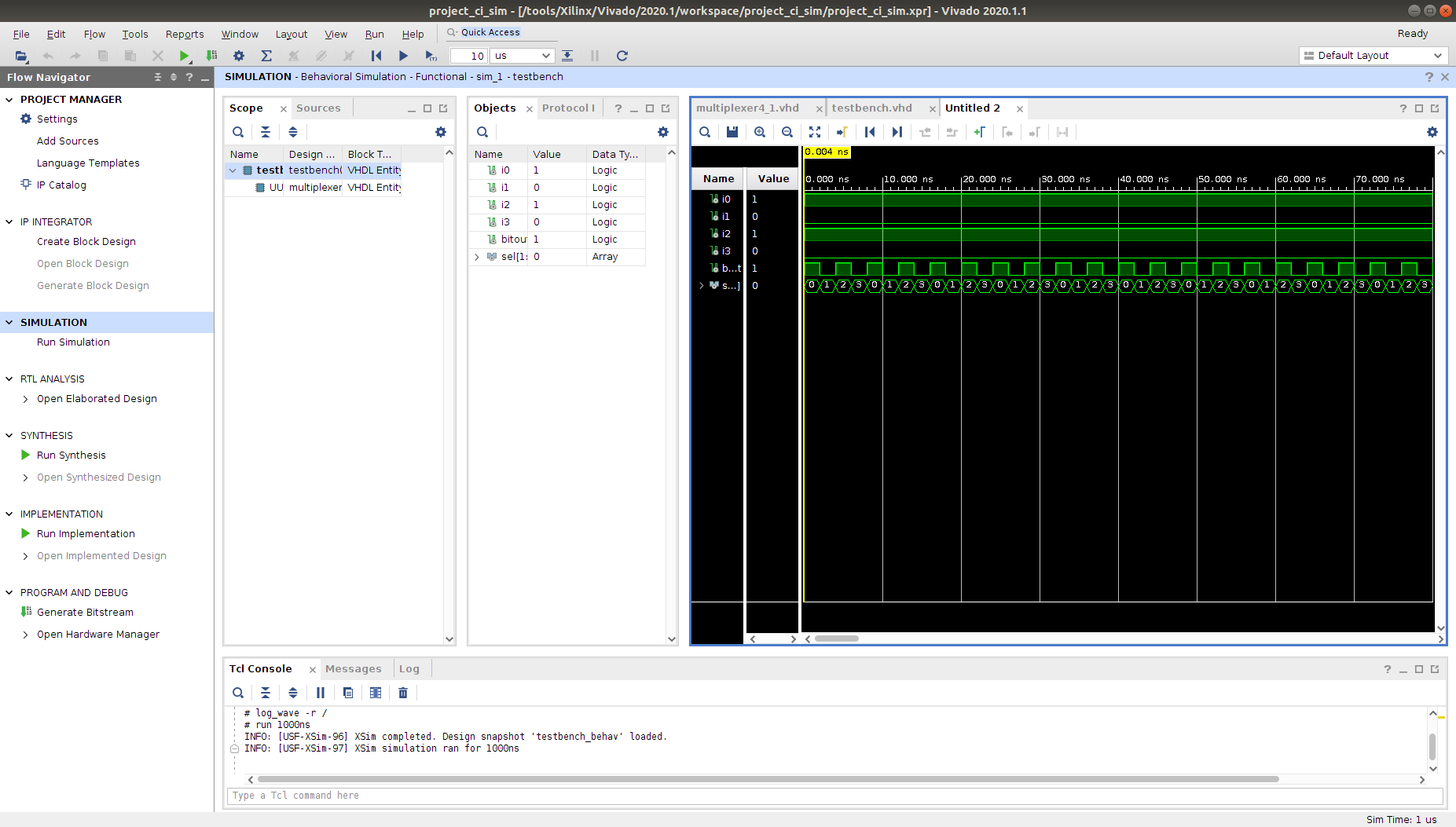
Our testbench works by importing our multiplexer as an entity. We then assign values to each one of the inputs i0-i4. Afterwards, we cycle through the various possible values of sel to observe how output has changed.
- In the
Flow Navigator, clickRun Simulationand Vivado will now display the the run simulation as shown below.
Running on BeetleboxCI
Now we have verified our multiplexer locally, we will integrate it with BeetleboxCI. Using BeetleboxCI will allow us to regularly iterate on the multiplexer, so any changes such as additional inputs or an enable signal can be automatically tested. It will also allow us to run simulations for long periods of time without using local computing resources, allowing us too focus on other parts of a system.
- Make a file in the project folder called
sim.tcland add the following code:
open_project ./project_ci_sim.xpr
set_property -name {xsim.simulate.log_all_signals} -value {true} -objects [get_filesets sim_1]
launch_simulation
sim.tcl is essentially a scripted version of the process we just ran manually. Scripting allows us to automate what we previously ran manually, allowing significant savings in development effort.- Make a folder called
.bbxin the same folder root directory and add a file calledconfig.yamlwith the following code:
runners:
 example-runner:
  image: ubuntu-vitis-2020-1

jobs:
 build_run_sim:
  runner: example-runner
  type:
   build: hardware
  current_working_directory: /tools/Xilinx/Vivado/2020.1/workspace/project_ci_sim
  output:
   artifact:
    - ./project_ci_sim.xpr
    - ./project_ci_sim.cache
    - ./project_ci_sim.hw
    - ./project_ci_sim.ip_user_files
    - ./project_ci_sim.sim
    - ./project_ci_sim.srcs
  steps:
   - run:
      name: Download files
      command: |
       source /tools/Xilinx/Vivado/2020.1/settings64.sh
       vivado -mode tcl -source sim.tcl
      type: miscellaneous
workflows:
 complete-build-test:
  jobs:
   - build_run_sim
The .bbx/config.yaml is the configuration file that BeetleboxCI will use to automate this application. Each project in BeetleboxCI consists of a pipeline, which is made of different workflows. Workflows are a series of jobs that are to be executed are configurable by the user in the configuration file under the workflows section. These jobs are then specified under the jobsand in our case we have a single job called build_run_sim. We specify the runner to be used as example-runner, which uses the machine image ubuntu-vitis-2020-1. This machine image is specifically designed to run Vitis and Vivado tools.
We also specify that the type is a build:hardware. This is an optional setting, but can be use to help identify what the purpose of this build is. The current_working_directory is used to set the working directory that the build will start from. If it is not set, it will by default be ~/.
We then identify the artifacts that are to be stored in the artifact store. Finally, we provide the steps that the job is to perform. We need to run commands in a bash shell, so we use the run command step. We provide name and the individual commands to be run in our bash shell through command. vivado -mode tcl -source sim.tcl executes the Tcl file, we produced earlier on Vivado. Using workflows we are able to automate the entire simulation process, but we now need to execute this environment by committing it to Github and linking BeetleboxCI to it.
- We need to ensure that only source code is committed to our Github repository and not large build files. To do so, we make a
.gitignorefile in the project root directory and add the following code:
#########################################################################################################
##    This is an example .gitignore file for Vivado, please treat it as an example as
##    it might not be complete. In addition, XAPP 1165 should be followed.
#########################################################################################################
#########
#Exclude all
#########
*
!*/
!.gitignore
###########################################################################
##    VIVADO
###########################################################################
#########
#Source files:
#########
#Do NOT ignore VHDL, Verilog, block diagrams or EDIF files.
!*.vhd
!*.v
!*.bd
!*.edif
#########
#IP files
#########
#.xci: synthesis and implemented not possible - you need to return back to the previous version to generate output products
#.xci + .dcp: implementation possible but not re-synthesis
#*.xci(www.spiritconsortium.org)
!*.xci
#*.dcp(checkpoint files)
!*.dcp
!*.vds
!*.pb
#All bd comments and layout coordinates are stored within .ui
!*.ui
!*.ooc
#########
#System Generator
#########
!*.mdl
!*.slx
!*.bxml
#########
#Simulation logic analyzer
#########
!*.wcfg
!*.coe
#########
#MIG
#########
!*.prj
!*.mem
#########
#Project files
#########
#XPR  +  *.XML ? XPR (Files are merged into a single XPR file for 2014.1 version)
#Do NOT ignore *.xpr files
!*.xpr
#Include *.xml files for 2013.4 or earlier version
!*.xml
#########
#Constraint files
#########
#Do NOT ignore *.xdc files
!*.xdc
#########
#TCL - files
#########
!*.tcl
#########
#Journal - files
#########
!*.jou
#########
#Reports
#########
!*.rpt
!*.txt
!*.vdi
#########
#C-files
#########
!*.c
!*.h
!*.elf
!*.bmm
!*.xmp
- Create a new Github Repository. Name the repository
project_ci_sim. - Now log into your BeetleboxCI web application which you have already installed.
- You will see the following screen, click
Add Project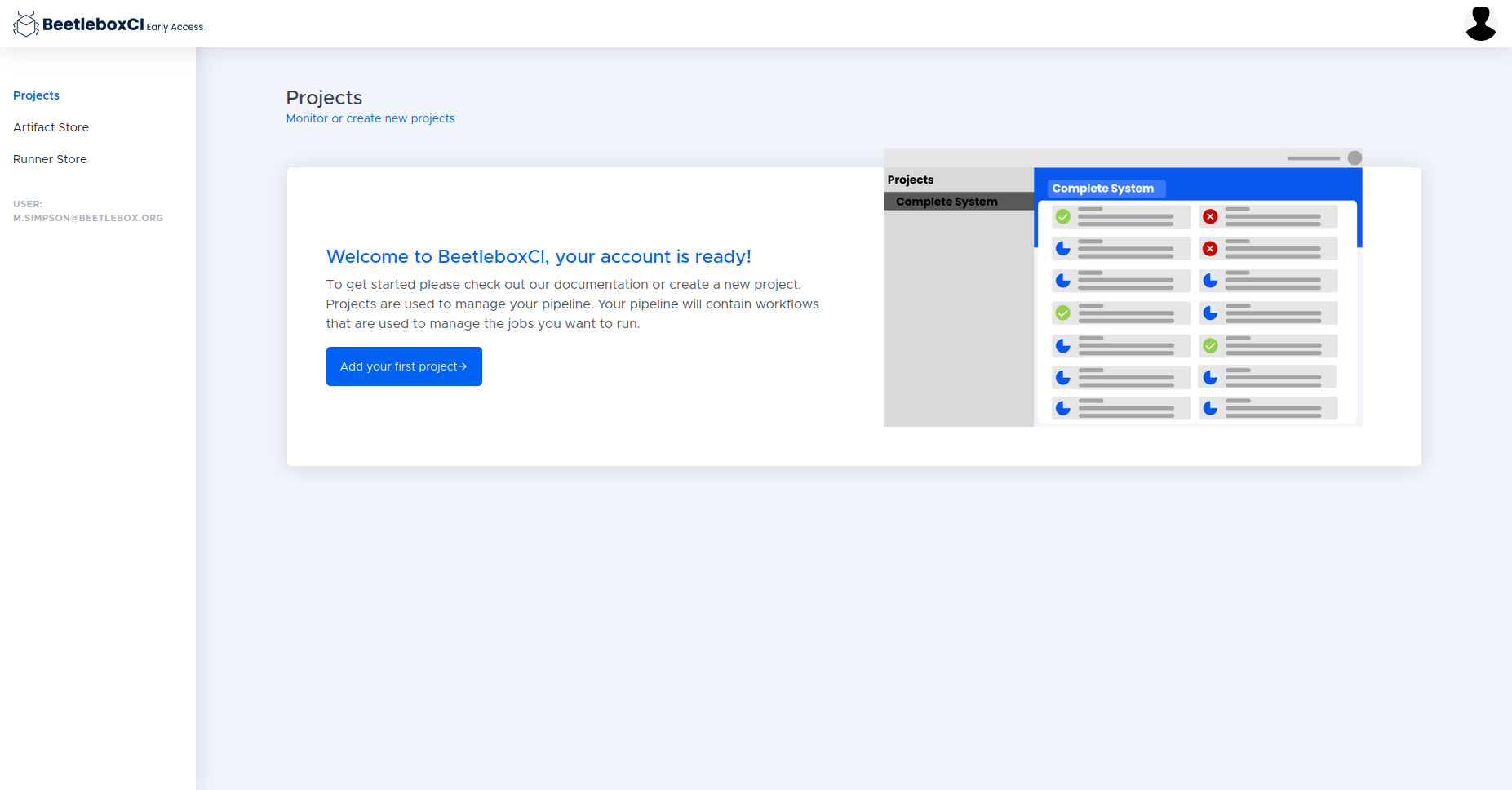
- Fill in the details for the project name, URL, and the Login details and click
Submit. - To run the pipeline on the CI, we must go into the pipeline and click the run button on the top right of the Workflows list.
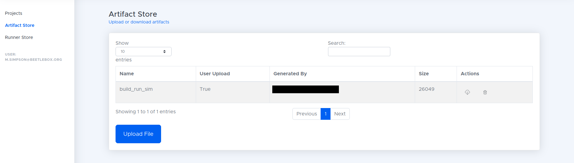
- When the build has finished in the CI navigate to the artifacts window and download the artifact using the cloud button as shown below.
Viewing our waveforms
Now that we have run our waveforms, we can view them through Vivado.
- Extract the downloaded zip file into a folder.
- Open Vivado and then select open project and open the
.xprfile in the extracted folder. - Now click
Flowin the top ribbon then clickOpen Static Simulation. - From here locate the file
testbench_behav.wdb, which should be in theproject_ci_sim.sim/sim_1/behav/xsimfolder. - In the scope folder, right click on the testbench and select
Add to wave window. This will display the waveforms run on the CI.
Editing our testbench
One of the major components of Continuous Integration is to make incremental changes that can then be continuously built and tested. To show an example of this, we will make a small change to our testbench and view the resulting waveform.