MicroPython
In the first part of the tutorial, we will learn how to use a special version of Python called MicroPython to program a simple LED Screen using BeetleboxCI. Python is the easiest way to get started with Raspberry Pis. We will be using a specific type of Python called MicroPython, which is designed for microcontrollers.
Pre-requisites
All needed hardware is supplied by the BeetleboxCI dev kit, but if you don't have a kit you can still follow the tuorial with the following hardware:
- A Raspberry Pi Pico
- A breadboard
- Jumper wires
- OLED Display Module I2C. Must be ssd1306 driver compatible. We use a 128X64 resolution.
You will also need the following software:
- An account with BeetleboxCI. You can sign up here.
- A Git provider. You can signup to GitHub for free.
Setting up MicroPython on the board
You first need to setup MircoPython on the board. You can find the instructions for doing so here, but we will cover it in this tutorial as well
- Download MicroPython from this link
- Press and hold the BOOTSEL button on the Pico board which is next to the USB port. Connect the Pico to your computer via the USB.
- This will make it appear to the computer as a Mass Storage Device. Drag and drop the file you just downloaded onto the Pico.
- Once dragged on, the board will reset and you will be running MicroPython
Connecting the Raspberry Pi to BeetleboxCI
Your next goal is to connect the Raspberry Pi Pico to a pipeline in BeetleboxCI. You will first need to create a repository and then run a simple piece of code of on the Pi to make sure it is running properly.
- Create a new git repository.
- Add the following file to the GitHub repository and call it
main.py. If you are using GitHub, you can just add the file in GitHUb by pressing theAdd filebutton on your repository.
from machine import Pin, Timer

led = Pin("LED", Pin.OUT)
tim = Timer()

def tick(timer):
 global led
 led.toggle()

tim.init(freq=2.5, mode=Timer.PERIODIC, callback=tick)
This is a simple example file will blink the in-built LED. It uses the machine.Pin library to control the pins on the board, whilst using machine.Timer to create a timer using the hardware clock on the raspberrypi. The tim timer is intialised so every 2.5 seconds the tick function toggles the led on and off.
- You now need to create a folder in the git repository called
.bbx. In this folder, insert the following into a file calledconfig.yaml:
runners:
 local-runner:
  image: [Your computer name]:5000/ubuntu-generic

jobs:
 build_run_sim:
  resource_spec: micro
  runner: local-runner
  privileged: True
  steps:
   - run:
      name: Setup Environment
      command: |
       apt-get -y update
       apt-get -y install python3-pip
       pip3 install adafruit-ampy
   - run:
      name: Connect to Pico
      command: |
       export LC_ALL=C.UTF-8
       export LANG=C.UTF-8
       export AMPY_PORT=/dev/ttyACM0
       ampy run main.py

workflows:
 complete-build-test:
  triggers:
   - push
  jobs:
   - build_run_sim
You will need to replace [Your computer name] with the name of your computer.
Explaining the configuration file
The config.yaml file contains all the information BeetleboxCI needs to set up an automatic pipeline to execute your code. Every pipeline is broken up into a series of workflows indicated by the workflows keyword. In this particular example, you have a single workflow called complete-build-test.
Each worflow is made up of jobs. A job is a series of commands that are executed in a closed environment known as a container. In this workflow, you have a single job called build_run_sim that is defined above. Each workflow also has a list of triggers that can be used to activate the jobs. For complete-build-test there is a single trigger in our list push. This trigger means that anytime new code is pushed into the repo, this workflow will run.
Taking a look at the build_run_sim job in the jobs, you can specify the exact steps that it is to execute. There are two steps named Setup Environment and Connect to Pico. The first step installs all the dependencies that are needed to connect to the Pico.
Ampy is a MicroPython tool that allows users to manipulate files and run code on MicroPython boards via the serial connection, including our communication tool ampy.
The second step then specifies what port the Pico is connected to via /dev/ttyACM0 line. The ampy run main.py line runs the main.py file and outputs the results.
You are able to specify the exact environment that these commands will run in through the different parameters of build_run_sim. Specifically, you can decide the container for the execution environment through the runner parameter. All runners are specified under the runners section at the top of the script. In this case, you are using the default ubuntu-generic image that is pre-installed with BeetleboxCI.
You can also specify the memory and computional resources through the resource_spec parameter. This is currently set to micro, which provides 2GB of RAM and half a virtual CPU.
Finally, since you are communicating to the board via USB, you will need the execution environment to have elevated priveleges to access the USB port. This is specified via the privileged: True command.
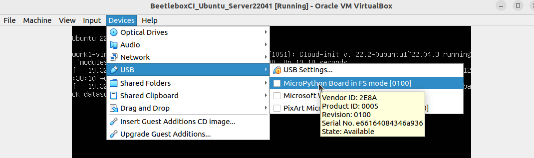
Before we run this workflow in BeetleboxCI, we need to ensure that the BeetleboxCI VM can detect the USB device that we have connected to the PC. We must run the following command on a terminal on the host machine to enable VirtualBox to detect USB devices, and then log out and log back in:
sudo usermod -aG vboxusers [your username]
- In the VM, go to Devices > USB > MicroPython Board in FS mode to allow the VM to access the Raspberry Pi.
- Now that we have finished setting up, start the BeetleboxCI VM and navigate to the web interface of BeetleboxCI (by default this is http://127.0.0.1:32767/ ) and connect the git repository to BeetleboxCI. You can find detailed instructions on how to do so here. Name the project
raspberry-pi-pico.
- To run your workflow, navigate to the
raspberry-pi-picopipeline page and press the play button.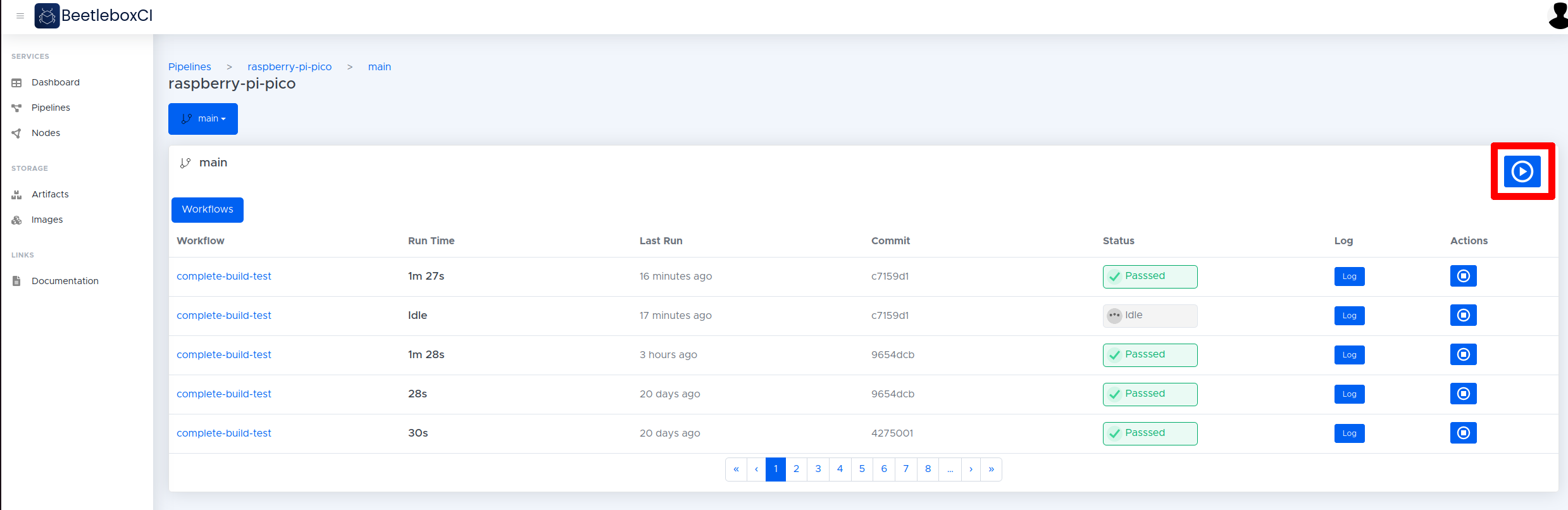
- If everything has been set up correctly, the LED on the Pico should begin blinking.
Connecting the LED screen
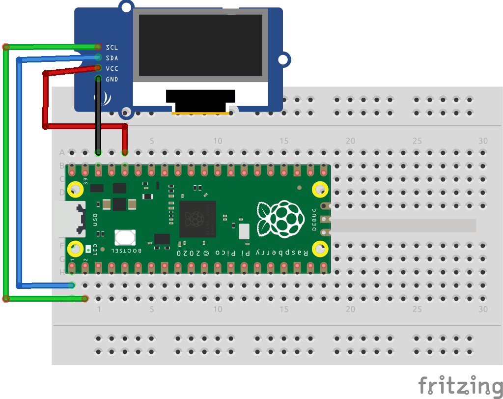
Now you have the Pico communicating with BeetleboxCI, you can perform more complex procedures like communicating with connected hardware components. You will be using a LED screen that is compatible with the ssd1306 driver that uses the i2c interface to communicate. You will then edit main.py to write an image to the screen. The first step though is connecting up the hardware.
- Connect the LED screen to the Pico as shown in the diagrams. SDA -> Pin 1, SCL -> Pin 2, GND-> Pin 38, VCC -> Pin 36.
- You now need to add the ssd1306 driver to the repo so that the Pico can communicate with the LED screen. You can find the ssd1306.py file here. Place this file inside your repository under a folder called
\lib. - Now you need to modify the
config.yamlfile so that thessd1306.pyfile and the\libfolder is transfered to the Pico:
runners:
 local-runner:
  image: work3-System-Product-Name:5000/ubuntu-generic

jobs:
 build_run_sim:
  resource_spec: micro
  runner: local-runner
  privileged: True
  steps:
   - run:
      name: Setup Environment
      command: |
       apt-get -y update
       apt-get -y install python3-pip
       pip3 install adafruit-ampy
   - run:
      name: Connect to Pico
      command: |
       export LC_ALL=C.UTF-8
       export LANG=C.UTF-8
       export AMPY_PORT=/dev/ttyACM0
       ampy put lib
       ampy run main.py

workflows:
 complete-build-test:
  triggers:
   - push
  jobs:
   - build_run_sim
The ampy put lib line will place the entire directory of \lib and all files contained onto the Pico.
4. You can then modify the main.py file with the following example:
# Wiring details
# SDA -> GP0
# SCL -> GP1
# VCC -> 3V3_EN 3.3 Volts
# GND -> GND


from machine import Pin, I2C
from ssd1306 import SSD1306_I2C
import framebuf
import utime

boardled = machine.Pin(25, machine.Pin.OUT) # Defines the green LED which is on the PICO Board.

WIDTH = 128 # oled display width
HEIGHT = 64 # oled display height

i2c = I2C(0,sda=Pin(0), scl=Pin(1), freq=400000) # Init I2C using , SCL=Pin(GP1), SDA=Pin(GP0), freq=400000
print("I2C Address 0X3C : "+hex(i2c.scan()[0]).upper()) # Display device address - should be 0X3C for a SSD1306 display, look at the ssd1306 driver
print("I2C Configuration: "+str(i2c)) # Display I2C config
devices = i2c.scan()

oled = SSD1306_I2C(WIDTH, HEIGHT, i2c, addr=0x3c) # Init oled display
# BeetleboxCI logo as 64x64 bytearray
buffer =bytearray(b'\x00\x0e\x00\x00\x00\x00`\x00\x00\x0e\x00\x00\x00\x00`\x00\x00\x0e\x00\x00\x00\x00`\x00\x00\x0e\x00\x00\x00\x00`\x00\x00\x0e\x00\x00\x00\x00`\x00\x00\x0e\x00\x00\x00\x00`\x00\x00\x0e\x00\x00\x00\x00`\x00\x00\x0f\x00\x00\x00\x01\xe0\x00\x00\x0f\xc0\x00\x00\x07\xe0\x00\x00\x03\xf0\x03\x80\x1f\xc0\x00\x00\x00\xfc\x07\xe0>\x00\x00\x00\x00<\x1f\xf08\x00\x00\x00\x00\x1c~\xfc0\x00\x00\x00\x00\x1d\xf8?0\x00\x00\x00\x00\x1b\xf0\x1f\xb0\x00\x00\x00\x00\x0f\xc0\x07\xe0\x00\x00\x00\x00?\x00\x01\xf8\x00\x00\x00\x00\xfc\x00\x00~\x00\x00\x00\x01\xf8\x00\x00?\x00\x00\x00\x07\xe0\x00\x00\x0f\xc0\x00\x00\x1f\x80\x00\x00\x03\xf0\x00\x00>\x00\x00\x00\x00\xfc\x00\x00|\x00\x00\x00\x00|\x00\x00~\x00\x00\x00\x00\xfc\x00\x00\x7f\x80\x00\x00\x03\xfc\x00\x00w\xe0\x00\x00\x0f\xdc\x00\x01\xf1\xf8\x00\x00\x1f\x1f\x00\x03\xf0\xfc\x00\x00~\x1f\x80\x07\xf0?\x00\x01\xf8\x1f\xe0\x1f\xf0\x0f\xc0\x07\xe0\x1f\xf0>p\x03\xf0\x0f\xc0\x1c\xf8\xfcp\x01\xf8?\x00\x1c~\xf8p\x00~\xfc\x00\x1c\x1e\xe0p\x00\x1f\xf0\x00\x1c\x0e\xf0p\x00\x0f\xe0\x00\x1c\x1epp\x00\x03\x80\x00\x1c\x1cxp\x00\x00\x00\x00\x1c<8p\x00\x00\x00\x00\x1c8<p\x00\x00\x00\x00\x1cx\x18p\x00\x00\x00\x00\x1c0\x18\xf0\x00\x00\x00\x00\x1e0\x03\xf0\x00\x00\x00\x00\x1f\x80\x07\xf0\x00\x00\x00\x00\x1f\xc0\x0f\xf0\x00\x00\x00\x00\x1f\xe0\x1fp\x00\x00\x00\x00\x1d\xf8~p\x00\x00\x00\x00\x1c\xfc\xf8p\x00\x00\x00\x00\x1c>\xf0p\x00\x00\x00\x00\x1c\x1epp\x00\x00\x00\x00\x1c\x1exx\x00\x00\x00\x00<<8|\x00\x00\x00\x00|<<?\x00\x00\x00\x01\xf8x\x1c\x0f\xc0\x00\x00\x07\xe0p\x1e\x03\xf0\x00\x00\x0f\xc0\xf0\x0e\x01\xf8\x00\x00?\x00\xe0\x0f\x00~\x00\x00\xfc\x01\xe0\x07\x00\x1f\x80\x03\xf0\x01\xc0\x07\x00\x07\xc0\x07\xe0\x01\xc0\x03\x00\x03\xf0\x1f\x80\x01\x80\x02\x00\x00\xfc~\x00\x00\x80\x00\x00\x00?\xf8\x00\x00\x00\x00\x00\x00\x1f\xf0\x00\x00\x00\x00\x00\x00\x07\xc0\x00\x00\x00\x00\x00\x00\x01\x00\x00\x00\x00')
fb = framebuf.FrameBuffer(buffer, 64, 64, framebuf.MONO_HLSB)

# Clear the oled display in case it has junk on it.
oled.fill(0)

# Blit the image from the framebuffer to the oled display
oled.blit(fb, 0, 0)

# Add some text
oled.text("I can",64,10)
oled.text("automate",64,25)
oled.text("Picos!",64,40)

# Finally update the oled display so the image & text is displayed
oled.show()
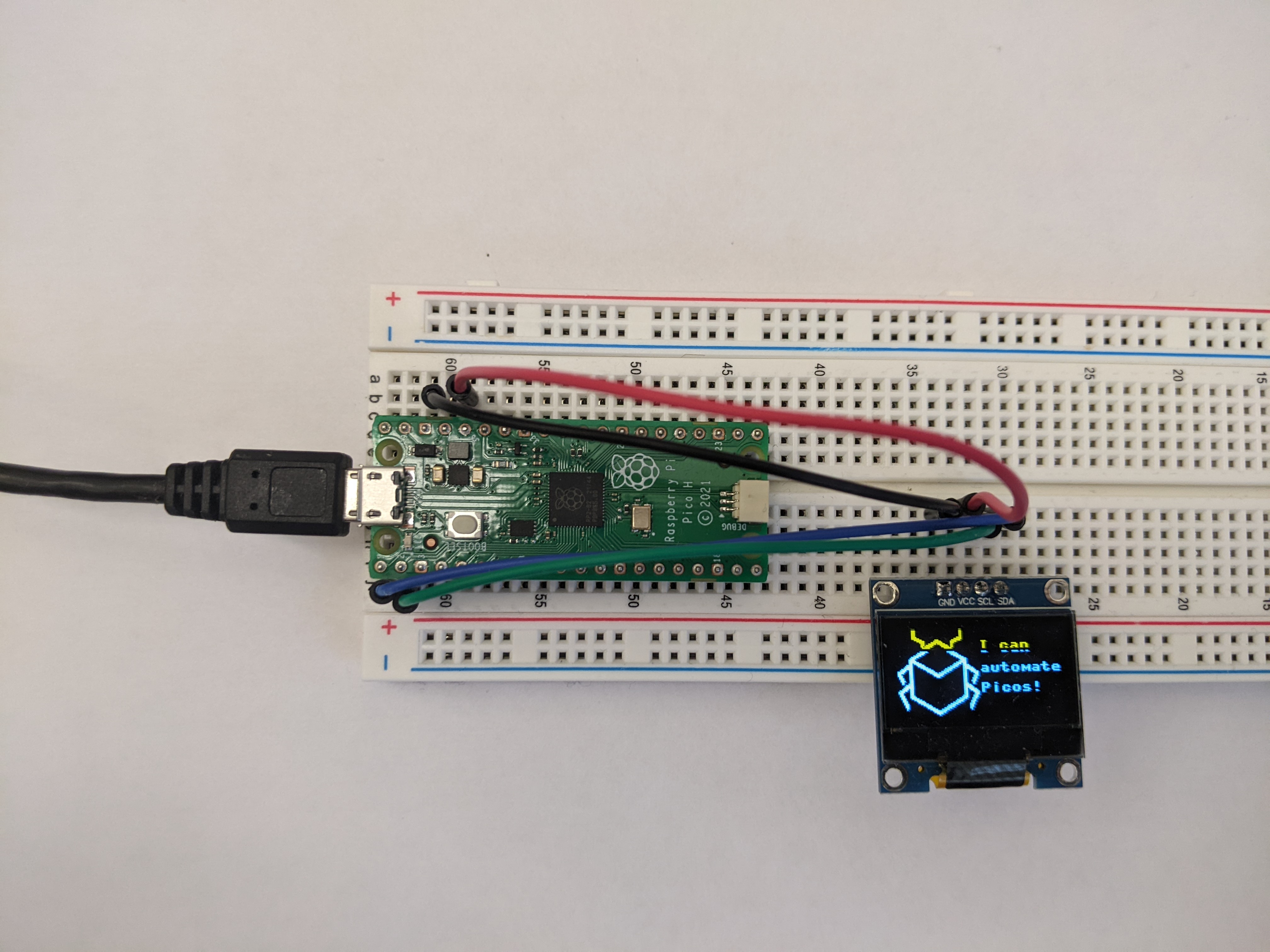
This example sets up the oled frame and displays the Beetlebox logo.
- Run the workflow like before. If everything is correct, you should see the OLED screen display with the Beetlebox logo and a small message.
Conclusion
Congratulations, you now know the basics of how to automate with Raspberry Pi Picos and MicroPython. In this tutorial, you managed to explore not just running software, but also uploading drivers and interfacing with hardware.
In the next part of this tutorial, you will explore using a C/C++ based development flow as opposed to MicroPython.