AMD (formerly Xilinx) FPGAs: Part 1 Setup and Logic Simulation
In this first part of the tutorial series, you will be setting up the CI environment to run logic simulation. You will learn how to set up and configure your continuous integration software to work with Vivado projects.
Prerequisites
- Get BeetleboxCI for free here! This tutorial will be referring to the machine that BeetleboxCI is installed on as a server, but BeetleboxCI can easily run on just a laptop.
- Download and install Vivado from the AMD website.
- A Git repository provider. You will use GitHub for this tutorial. BeetleboxCI does support a range of different Git repository providers, which you can find here.
- Make sure that the Git repo provider is linked to your BeetleboxCI account
- Make sure to have Git installed on your computer as well.
- An AMD (formerly Xilinx) FPGA. For this you will be using the Arty A7-100 FPGA Development Board. You can use other FPGA boards but will need to modify when the Arty A7 is specifically referenced.
Setting up your Vivado project
Creating a new Vivado project
- Ensure that your Development Board is connected to your machine that is currently running BeetleboxCI.
- In Vivado, create a new project. Choose
File>Project>New.... - In the
New Projectwindow, hitNext >. Then name the projectci_for_fpgasand choose where you wish to store the project. Then clickNext >. - For
Project TypeselectRTL Project - For
Default PartselectBoardsand then selectArty A7 100and clickNext. You may need to download the files if you have not done so previously. - In
New Project Summary, clickFinish. Let Vivado finish creating the files.
Creating your full adder design
Now you have created your project, you need to create a simple adder design to synthesize. If you have your own designs that you want to try, you can use them instead of creating a new one.
- Under
Project Manager, clickAdd Sources. In theAdd Sourceswindow, selectAdd or create design sourcesand then clickNext. - In the next window click
Create Fileand selectVHDLforFile Type. For File name, provideAdder. Then selectOKand then clickFinish. - A
Define Modulewindow should appear. SelectOK. - In the
Sourcestab, underDesign Sourcesclickadderthen use the following code to implement a full adder:
library IEEE;
use IEEE.STD_LOGIC_1164.ALL;

entity adder is
  Port ( A : in STD_LOGIC;
    B : in STD_LOGIC;
    CIN: in STD_LOGIC;
    S: out STD_LOGIC;
    COUT: out STD_LOGIC);
end adder;

architecture Behavioral of adder is
begin
    S <= A xor B xor CIN;
    COUT <= (A and B) or (CIN and (A xor B));

end Behavioral;
Creating the Testbench
The very first stage of any FPGA testing is to simulate the design. To do this we need to provide a testbench for our adder:
- Under
Project Manager, clickAdd Sources. In theAdd Sourceswindow, selectAdd or create simulation sourcesand then clickNext. - In the next window click
Create Fileand selectVHDLforFile Type. For File name, provideadder_testbench. Then selectOKand then clickFinish. - In the
Define Modulewindow, clickOK. - In the
Sourcestab, underSimulation Sourcesclickadder_testbenchthen place the following code in for our testbench:
library IEEE;
use IEEE.STD_LOGIC_1164.ALL;

entity adder_testbench is
end adder_testbench;

architecture Behavioral of adder_testbench is

    component adder
        Port ( A : in STD_LOGIC;
            B : in STD_LOGIC;
            CIN: in STD_LOGIC;
            S: out STD_LOGIC;
            COUT: out STD_LOGIC);
    end component;

    signal signal_A : STD_LOGIC :='0';
    signal signal_B : STD_LOGIC :='0';
    signal signal_CIN : STD_LOGIC :='0';
    signal signal_S : STD_LOGIC;
    signal signal_COUT : STD_LOGIC;

begin

    dut: component adder
        port map (
            A => signal_A,
            B => signal_B,
            CIN => signal_CIN,
            S => signal_S,
            COUT => signal_COUT
        );

    stimulus:
        process begin
            wait for 10ns;
            signal_A <= '1';
            signal_B <= '0';
            wait for 2ns;
            assert signal_S = '1';
            assert signal_COUT = '0';
            wait for 8ns;
            signal_A <= '0';
            signal_B <= '1';
            wait for 2ns;
            assert signal_S = '1';
            assert signal_COUT = '0';
            wait for 8ns;
            signal_A <= '1';
            signal_B <= '1';
            wait for 2ns;
            assert signal_S = '0';
            assert signal_COUT = '1';
            wait for 8ns;
            assert 0 = 1;
            wait for 10ns;
        end process stimulus;
end Behavioral;
The testbench is relatively simple. It instantiates the adder component and then connects to its inputs and outputs. Afterwards it begins the stimulus process which waits for 10 ns before driving signal_A and signal_B. It then checks the outputs of signal_S and signal_COUT through assert statements. It then repeats the process with different stimulus values. At the very end, there is the line assert 0=1;. This is to deliberately trigger an error and you will see how to handle errors in CI later in this tutorial.
Running your testbench
Now that you have your testbench, it is time to test it out.
- On the left-hand column of Vivado, click
Run SimulationunderSimulation. Then clickRun Behavioral Simulation. This will open up theSimulationtab that will look like the following: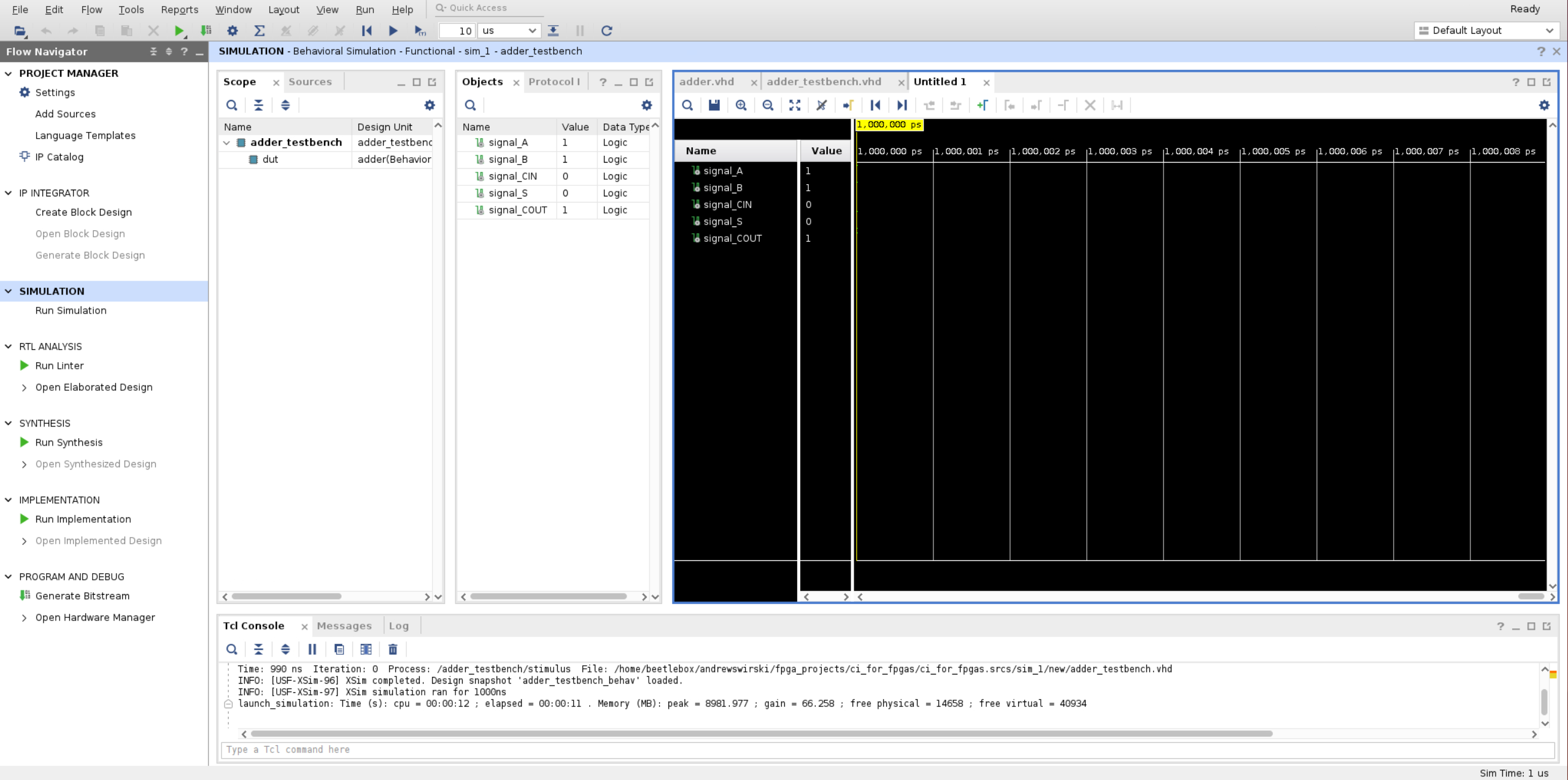
- In the toolbar, change the
run fortime to60nsand then press theRun Forbutton: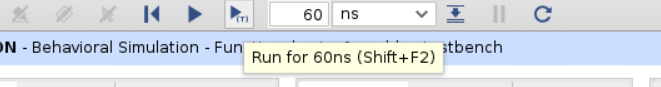
- Your simulation should now run for 60ns and should look like this:
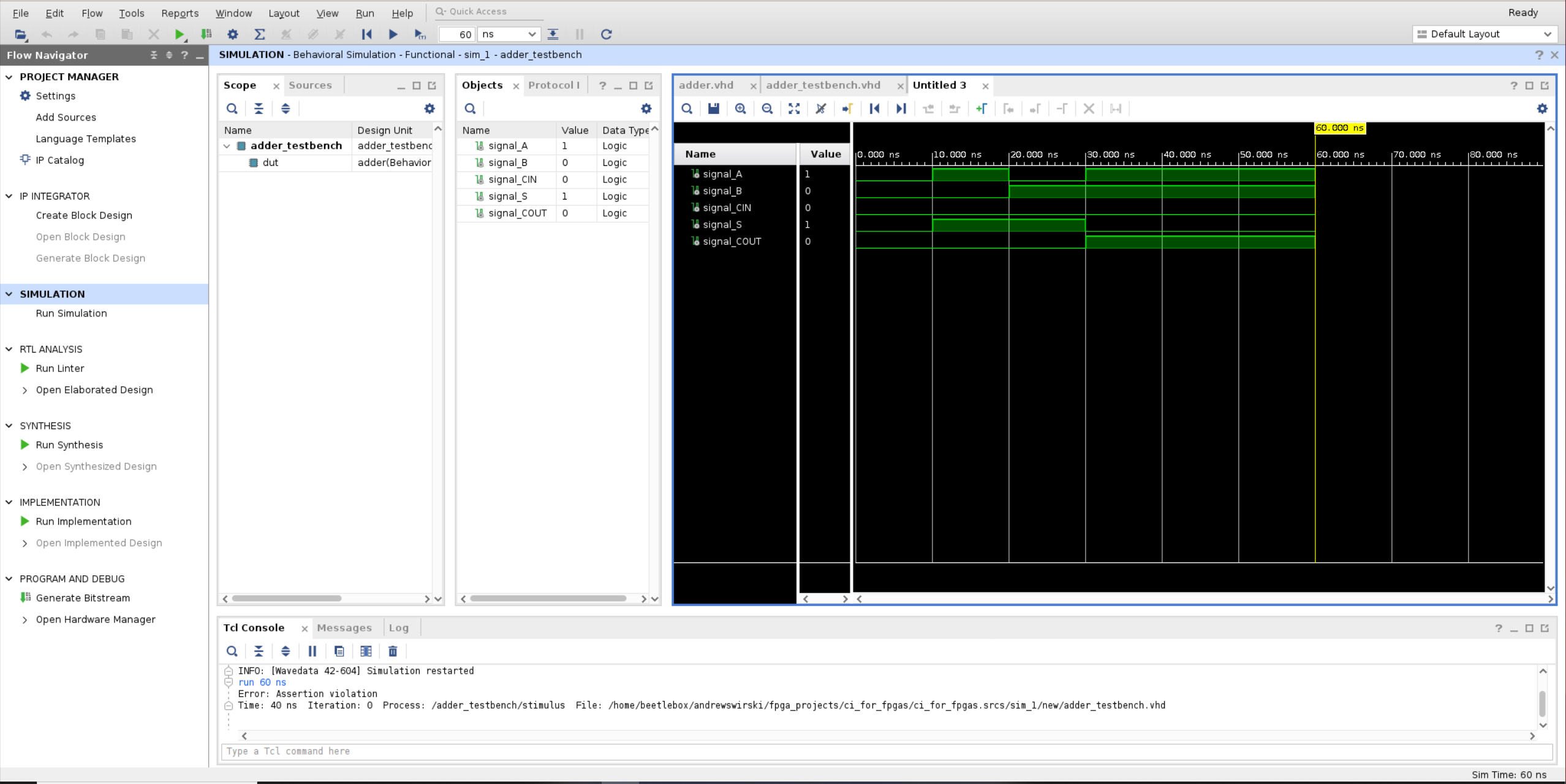 The TCL console should report an assertion violation:
run 60 ns
Error: Assertion violation
Time: 40 ns  Iteration: 0  Process: /adder_testbench/stimulus  File: <your_directory>/ci_for_fpgas/ci_for_fpgas.srcs/sim_1/new/adder_testbench.vhd
You now have a design and testbench that you can run in a ci pipeline.
Setting up your Git repository
Now you have your project, it is time to initialize the Git repository and push it to GitHub. For every project, it is recommended to set up the Git repository from the very beginning to make it easier to track changes and share your project.
For this tutorial, you will be using GitHub, but BeetleboxCI supports a variety of Git repo providers that you may wish to use instead.
- Git repositories should only contain source files, but Vivado produces a lot of different files during the simulation process that you need to filter out. To do this, create a new file in your project directory called
.gitignoreand place the following in it:
# Blocklist files/folders in same directory as the .gitignore file
/*

# Includelist some files
!.gitignore
!README.md

# Include xpr and srcs
!ci_for_fpgas.srcs/
!ci_for_fpgas.srcs/*
!ci_for_fpgas.xpr

# Include user generated tcl scripts
!tcl_scripts/
!tcl_scripts/*
This configuration will ignore all files except for the project file, source files, and specified exceptions.
- Create a new repository on GitHub, call it
amd-fpga-ci-tutorial, and make sure to leave it empty (don't add a readme). Here is a guide from GitHub. You should see the following screen: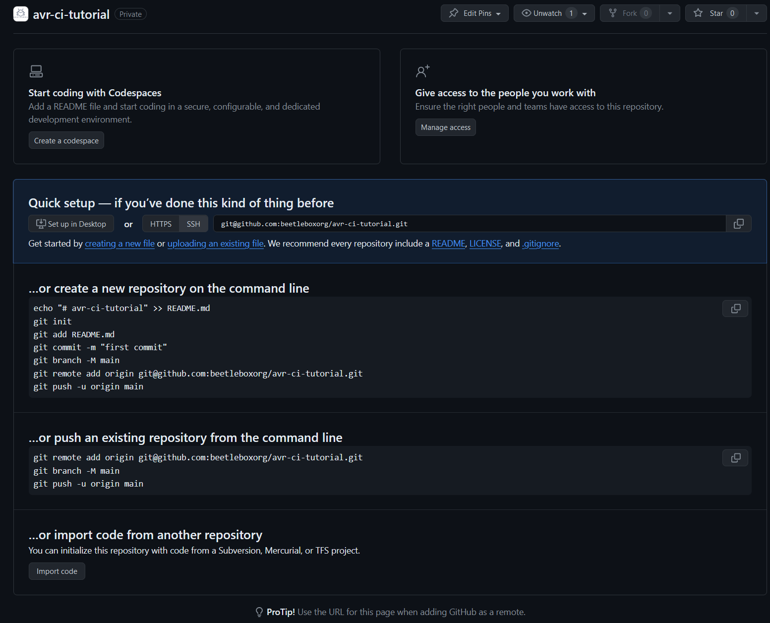
- Follow the
…or create a new repository on the command lineinstructions using your project. Launch a terminal in the directory of your project and run the following commands:
git init
git add .
git commit -m "first commit"
git branch -M main
git remote add origin git@github.com:beetleboxorg/amd-fpga-ci-tutorial.git
git push -u origin main
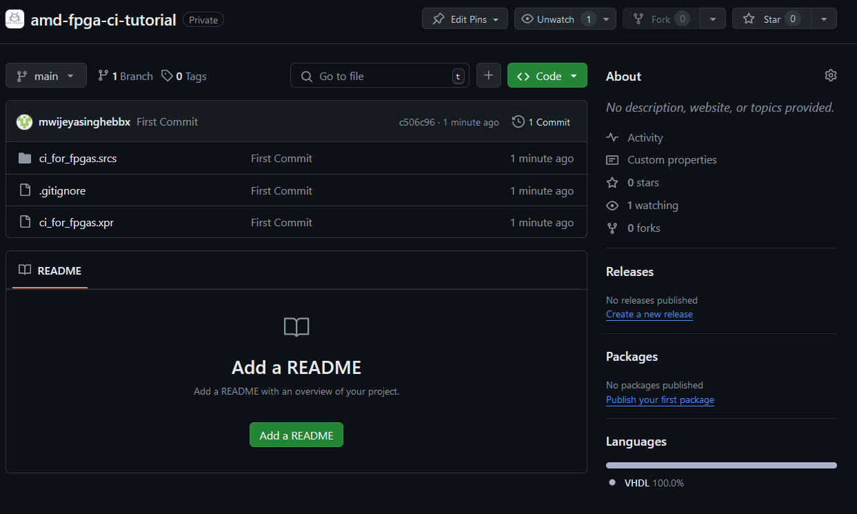
- In GitHub, you should see your files added to your repository.
Creating a tcl script for your testbench
When you run your TCL script for your testbench, you typically use the Vivado interface. However, you cannot use this interface when running a CI pipeline. However, Vivado is designed so that every action has a corresponding TCL command. You will now create a tcl script that runs the simulation and place it in your git repository.
- In your project folder, create a new folder called
tcl_scripts. - In Vivado, select
File>Text Editor>New Fileand then create a new file calledrun_sim.tcl. Then clicksave. - Copy the following into
run_sim.tcl:
open_project ci_for_fpgas.xpr
set_property -name {xsim.simulate.log_all_signals} -value {true} -objects [get_filesets sim_1]
launch_simulation
restart
run 60 ns
This script does the actions you performed earlier in Vivado as a repeatable script. 4. Update your Git repository to include this file by executing the following commands in your terminal:
git add .
git commit -m "Added tcl script"
git push
Linking the Git Repository
Now you have your Git repo ready, you can link it to GitHub. For this step, if you have not already done so, you will need to link your GitHub account to BeetleboxCI.
- Open up BeetleboxCI on your web browser and click the
Pipelinespage. On this page, selectCreate Pipelineat the bottom. - On the
Create New Pipelinepage, search for your repo on theGitHubtab and selectCreate Pipeline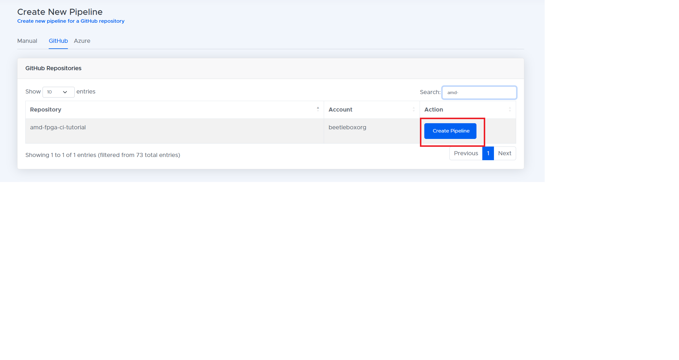
- You will be greeted by the
Set up pipeline config for amd-fpga-ci-tutorialpopup. Clickyesand then select themainbranch. This will create a.bbx/config.yamlfile in the branch. - You will then be met with the
Empty Config Filepopup. Selectnobecause you will be pasting in your own config file. - Copy the following pipeline into the blank config file. You need to replace
<path_to_xilinx_tools_directory by default this is /tools/Xilinx>and<path_to_vivado_installation_directory by default this is /tools/Xilinx/Vivado/2023.1/>inRun Simulationwith your Vivado installation location as well as version number. Then clickSave and commit.
# Define a runner that will be used to run a job
runners:
 ubuntu-runner:
  image: public.ecr.aws/y2s4f3y9/ubuntu-generic

# Define a job to be performed during a workflow
jobs:
 run-sim-job:
  # Specify the runner used to perform this job
  runner: ubuntu-runner
  output:
   artifact:
    - ci_for_fpgas.sim/
  volumes:
    - mount:
        name: volume1
        path: <path_to_xilinx_tools_directory by default this is /tools/Xilinx>

  # Define one or more steps to execute commands as part of the job
  steps:
   - run:
      name: Initalise vivado environment
      command: |
        apt-get update
        apt-get install locales
        locale
        locale-gen "en_US.UTF-8"
        update-locale LANG=en_US.UTF-8
   - run:
      name: Run Simulation
      command: |
        cd  <path_to_vivado_installation_directory by default this is /tools/Xilinx/Vivado/2023.1/>
        source settings64.sh
        cd $HOME
        ls
        vivado -mode batch -source tcl_scripts/run_sim.tcl  | tee simulation_output.txt
   - run:
      name: Parse simulation for errors
      command: |
        # Path to the file to be checked
        FILE_PATH="./simulation_output.txt"
        # Check if the file exists
        if [[ ! -f "$FILE_PATH" ]]; then
         echo "File does not exist: $FILE_PATH"
          exit 1
        fi
        # Search for the phrase "Error: Assertion violation" in the file
        if grep -q "Error: Assertion violation" "$FILE_PATH"; then
          echo "Error: Assertion violation found in file."
          exit 1
        else
          echo "No assertion violations found. Passing."
          exit 0
        fi

# Define a workflow to orchestrate a job
workflows:
 run-sim-workflow:
  jobs:
   - run-sim-job
Once committed you will be redirected to the pipeline page, you may be greeted by an error saying that no pipeline has been found. If this is the case then click the
refreshbutton that will reload the config file. You should now be greeted by the following pipeline: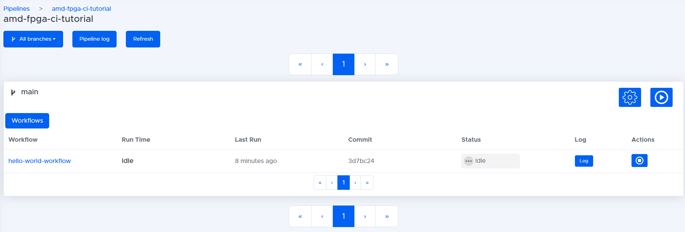
Click the
Run Workflowplay button on the right-hand side and clickYesin response to the warning. This will now launch your pipeline and should fail with a red cross. You now have run your first FPGA simulation pipeline.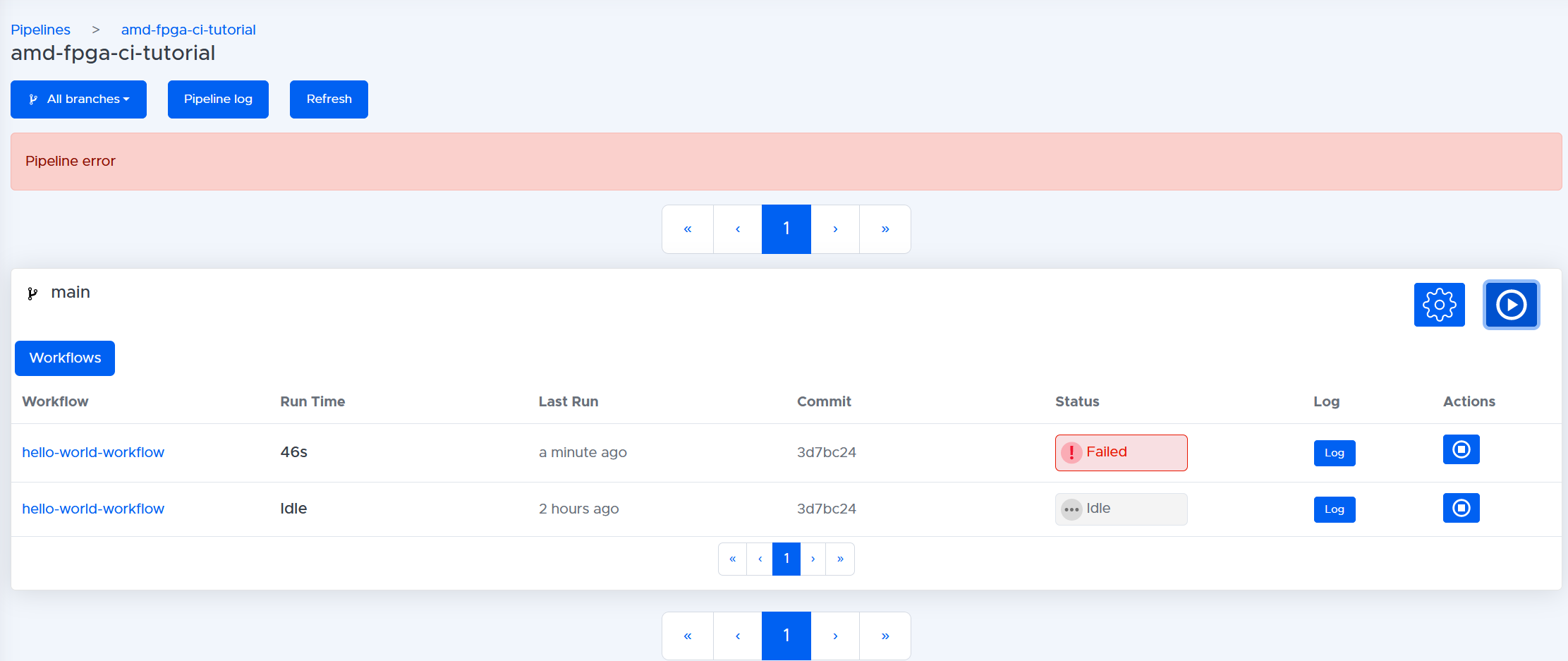
You can see the results of your pipeline by clicking on the name of the workflow
run-sim-workflowthen on the workflow page clicking the jobrun-sim-job. This will take you to the job page. In this job page, you can view all the steps and their logs. The stepParse simulation for errorsshould have failed.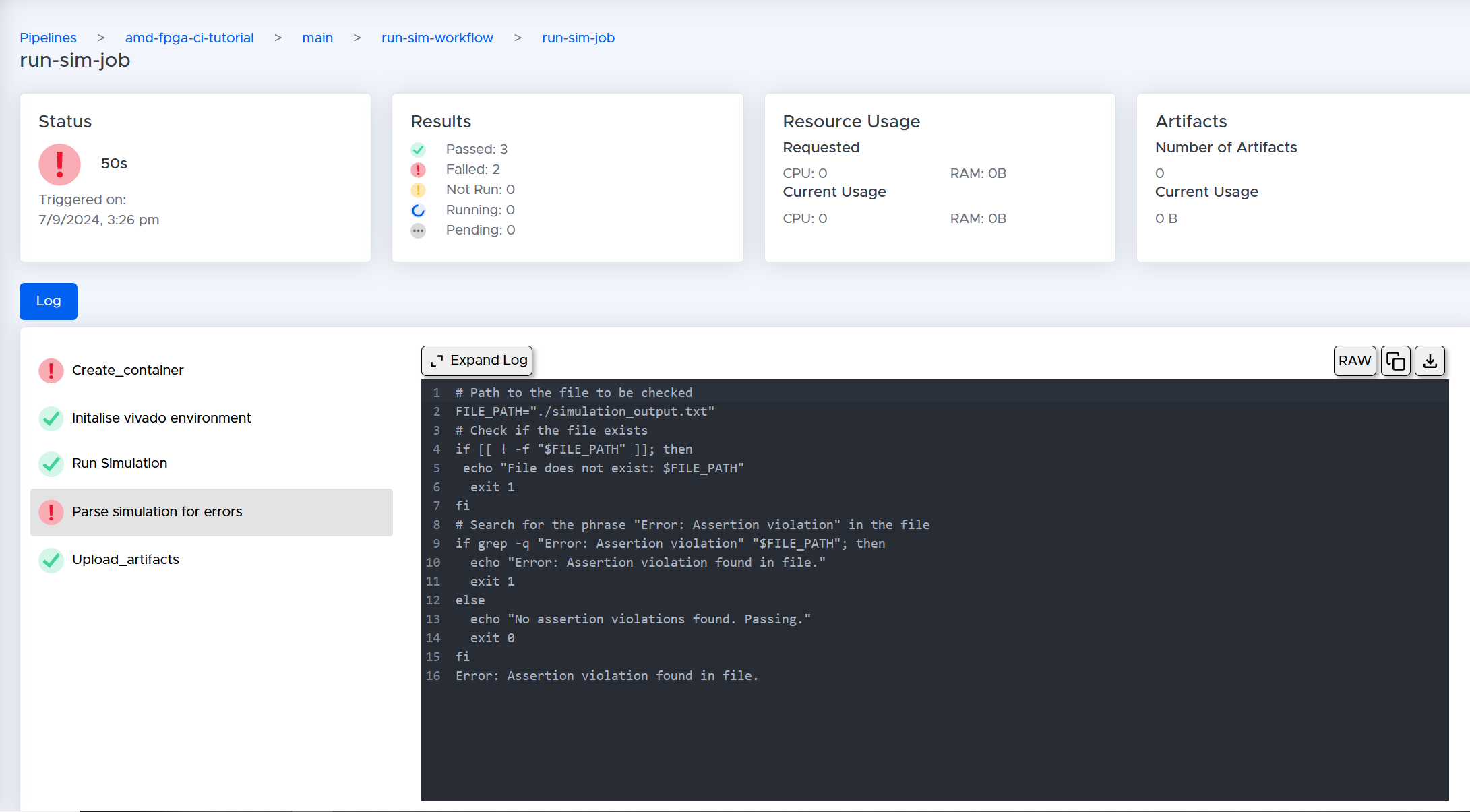 The log tells us that the simulation has an assertion violation found in the file:
# Path to the file to be checked
FILE_PATH="./simulation_output.txt"
# Check if the file exists
if [[ ! -f "$FILE_PATH" ]]; then
 echo "File does not exist: $FILE_PATH"
  exit 1
fi
# Search for the phrase "Error: Assertion violation" in the file
if grep -q "Error: Assertion violation" "$FILE_PATH"; then
  echo "Error: Assertion violation found in file."
  exit 1
else
  echo "No assertion violations found. Passing."
  exit 0
fi
Error: Assertion violation found in file.
Explaining your pipeline.
Now that you have the pipeline running, you can take a deeper look at how the simulation is being executed. Each pipeline consists of multiple workflows. You can think of a workflow as a single automated process from source code to deliverable code.
# Define a workflow to orchestrate a job
workflows:
 run-sim-workflow:
  jobs:
   - run-sim-job
In this case, you have a single workflow called run-sim-workflow. Each workflow will then run one or more jobs. A job is a series of tasks that are to be run on a single independent execution environment known as a container. Every job will run independently and in parallel with one another until BeetleboxCI runs out of processing capacity. In the run-sim-workflow, you have a single job to run called run-sim-job:
runners:
 ubuntu-runner:
  image: public.ecr.aws/y2s4f3y9/ubuntu-generic

# Define a job to be performed during a workflow
jobs:
 run-sim-job:
  # Specify the runner used to perform this job
  runner: ubuntu-runner
In the jobs section, you can define the type of container in which the job is going to execute, known as a runner. You can define a runner in the runners section. Each runner must have an image and you can think of an image as a snapshot in time of a pre-built container. In this case, there is a single runner called ubuntu-runner and that runner is using the image public.ecr.aws/y2s4f3y9/ubuntu-generic:latest. This is a pre-built container that has a generic version of Ubuntu Linux attached.
jobs:
 run-sim-job:
  ...
  output:
   artifact:
    - ci_for_fpgas.sim/
  volumes:
    - mount:
        name: volume1
        path: <path_to_xilinx_tools_directory by default this is /tools/Xilinx>
...
You also will want access to the simulation files so that you can check the waveforms if something goes wrong. To do this, you can use the output keyword, followed by artifact. An artifact is just a folder or file that you want to store in the artifact repository. In this case, you want to store the folder ci_for_fpgas.sim/, which contains the simulation folder and the waveforms.
For the container to run Vivado, it needs to have access to it. To gain access, you can mount the folder where Vivado is installed on your host machine. To mount, you use the volume keyword followed by - mount. You then need to provide a name for the volume volume1 followed by the directory where your Xilinx tools are stored. By default this is /tools/Xilinx. Note that volumes are read-only and that the container may not write to this path.
  steps:
   - run:
      name: Initalise vivado environment
      command: |
        apt-get update
        apt-get install locales
        locale
        locale-gen "en_US.UTF-8"
        update-locale LANG=en_US.UTF-8
You are now onto the steps section of the pipeline. Each job runs a series of sequential steps. To use Vivado, you first must update the locale of Vivado to en_US.UTF8.
   - run:
      name: Run Simulation
      command: |
        cd  <path_to_vivado_installation_directory by default this is /tools/Xilinx/Vivado/2023.1/>
        source settings64.sh
        cd $HOME
        ls
        vivado -mode batch -source tcl_scripts/run_sim.tcl  | tee simulation_output.txt
To run Vivado, you need to first source its settings64.sh file, which is located in the installation directory of Vivado. You then use cd $HOME to return to a directory where there is write access. You can now run the script you created for simulation through Vivado's batch mode through vivado -mode batch -source tcl_scripts/run_sim.tcl. The | tee simulation_output.txt command allows you to write the output of Vivado to simulation_output.txt and to the terminal simultaneously. You can then parse tee simulation_output.txt to see if any assertion errors have occurred.
   - run:
      name: Parse simulation for errors
      command: |
        # Path to the file to be checked
        FILE_PATH="./simulation_output.txt"
        # Check if the file exists
        if [[ ! -f "$FILE_PATH" ]]; then
         echo "File does not exist: $FILE_PATH"
          exit 1
        fi
        # Search for the phrase "Error: Assertion violation" in the file
        if grep -q "Error: Assertion violation" "$FILE_PATH"; then
          echo "Error: Assertion violation found in file."
          exit 1
        else
          echo "No assertion violations found. Passing."
          exit 0
        fi
To parse the simulation, you can use this script to check simulation_output.txt. As observed in the logs, this script outputs Error: Assertion violation found in file., if an assertion error is found in the log; otherwise, it indicates success.
Getting your pipeline to succeed.
Now that you have seen how to catch assertion errors, you can change your testbench to prevent the assertion error from occurring.
- Change your
adder_testbench.vhdto comment outassert 0=1. Make sure to add, commit and push this file back to your Git repo.
library IEEE;
use IEEE.STD_LOGIC_1164.ALL;

entity adder_testbench is
--  Port ( );
end adder_testbench;

architecture Behavioral of adder_testbench is

    component adder
        Port ( A : in STD_LOGIC;
            B : in STD_LOGIC;
            CIN: in STD_LOGIC;
            S: out STD_LOGIC;
            COUT: out STD_LOGIC);
    end component;

    signal signal_A : STD_LOGIC :='0';
    signal signal_B : STD_LOGIC :='0';
    signal signal_CIN : STD_LOGIC :='0';
    signal signal_S : STD_LOGIC;
    signal signal_COUT : STD_LOGIC;

begin

    dut: component adder
        port map (
            A => signal_A,
            B => signal_B,
            CIN => signal_CIN,
            S => signal_S,
            COUT => signal_COUT
        );

    stimulus:
        process begin
            wait for 10ns;
            signal_A <= '1';
            signal_B <= '0';
            wait for 2ns;
            assert signal_S = '1';
            assert signal_COUT = '0';
            wait for 8ns;
            signal_A <= '0';
            signal_B <= '1';
            wait for 2ns;
            assert signal_S = '1';
            assert signal_COUT = '0';
            wait for 8ns;
            signal_A <= '1';
            signal_B <= '1';
            wait for 2ns;
            assert signal_S = '0';
            assert signal_COUT = '1';
            wait for 8ns;
            -- assert 0 = 1;
            wait for 10ns;
        end process stimulus;

end Behavioral;
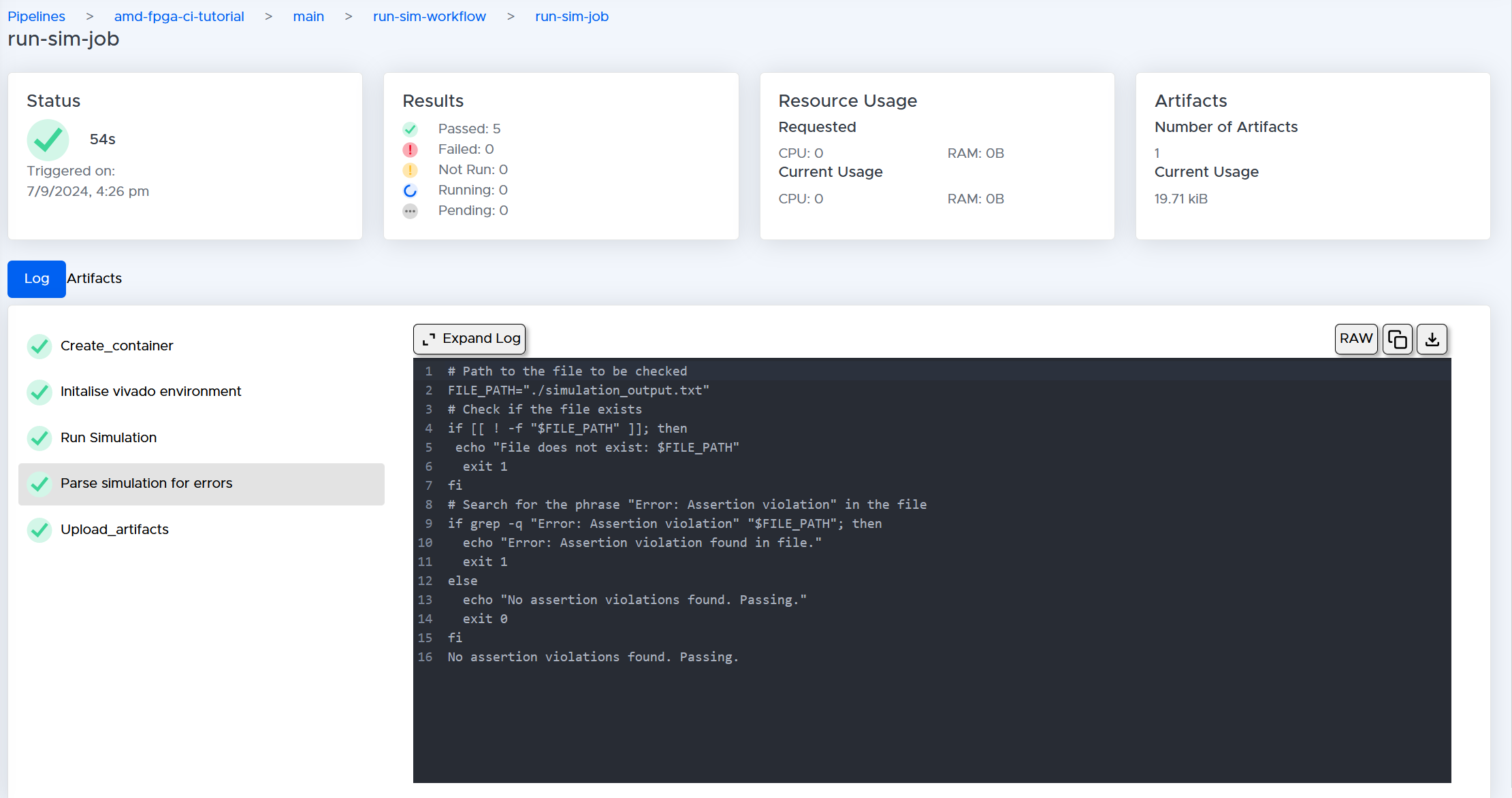
- Rerun your pipeline and it should now succeed:
Opening up your simulation.
You can also open the simulation to check the waveforms by downloading the simulation folder.
- You can download the folder by going to the artifacts section and selecting the
run-sim-job_4917.tar.gzdownload button.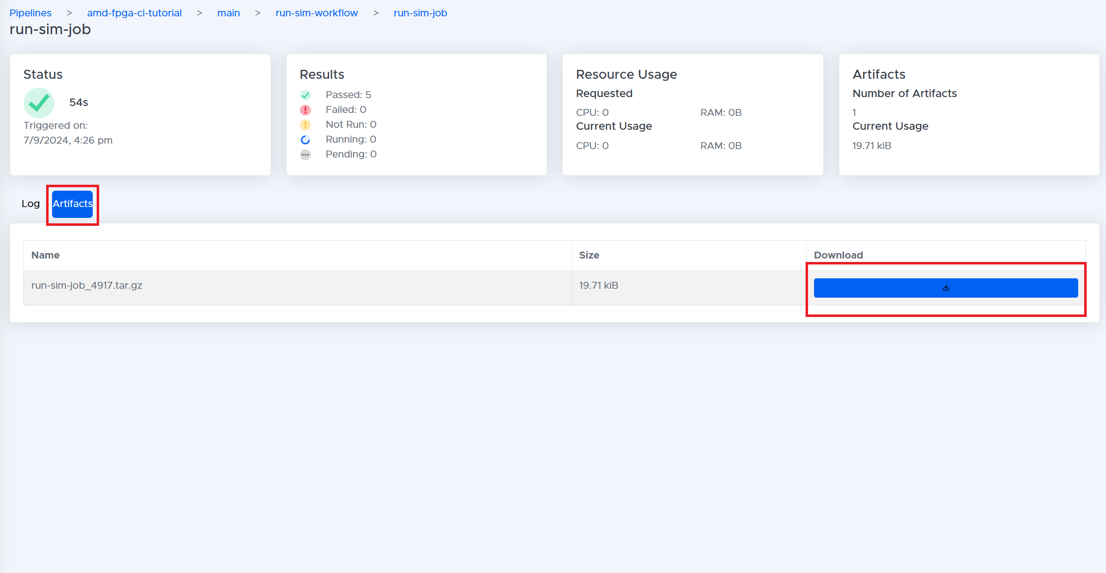
- Extract the folder and find the
adder_testbench_behav.wdbfile. This contains our waveform. - To open it up, go back to Vivado GUI and then in the toolbar select
Flow>Open Static Simulation...and in the new window selectadder_testbench_behav.wdb. This will open the wave database.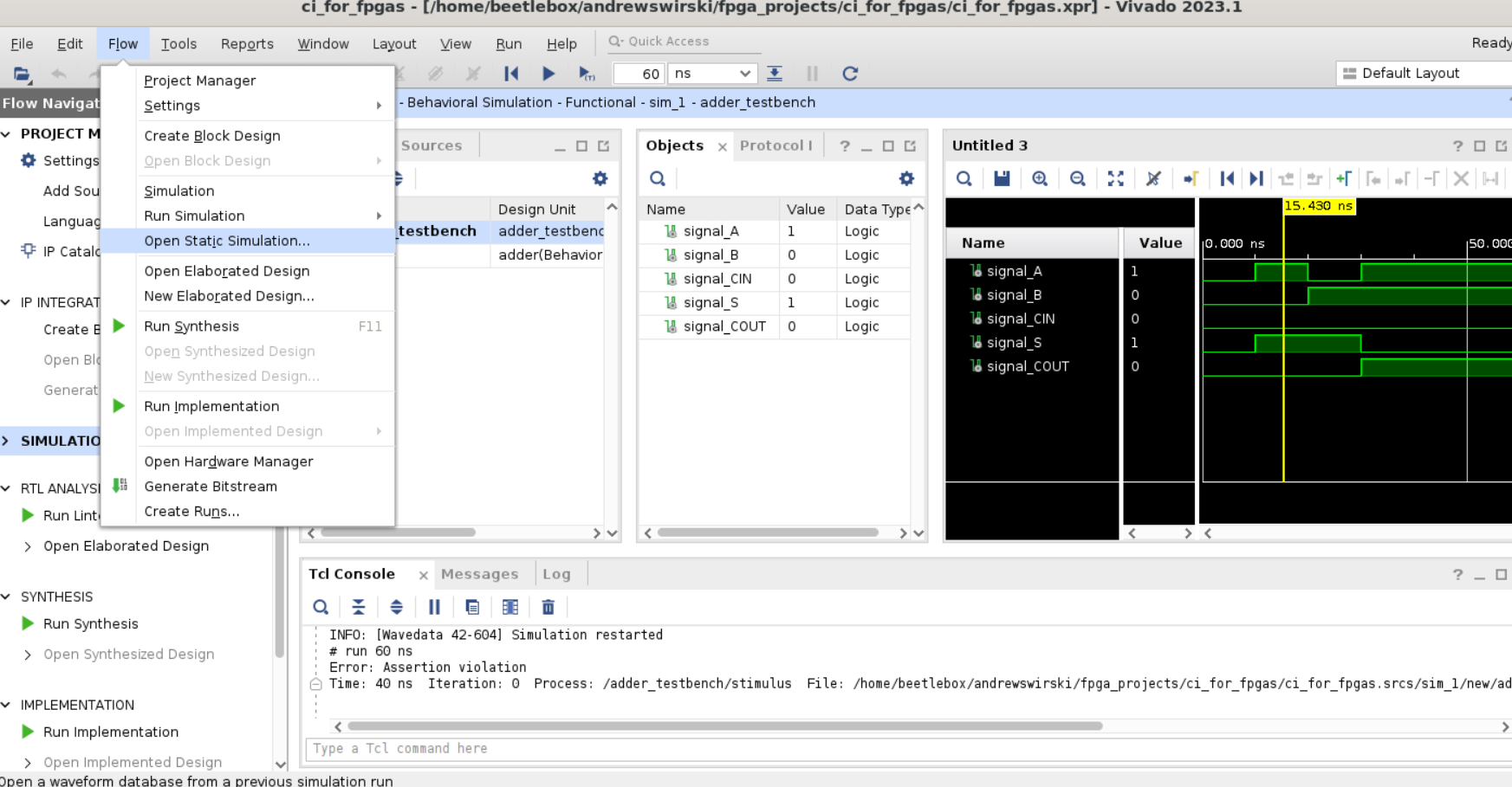
- To see the waveforms in the
Objectstab select the signals and right-clickAdd to wave window. This will display the resulting signals that you can then examine.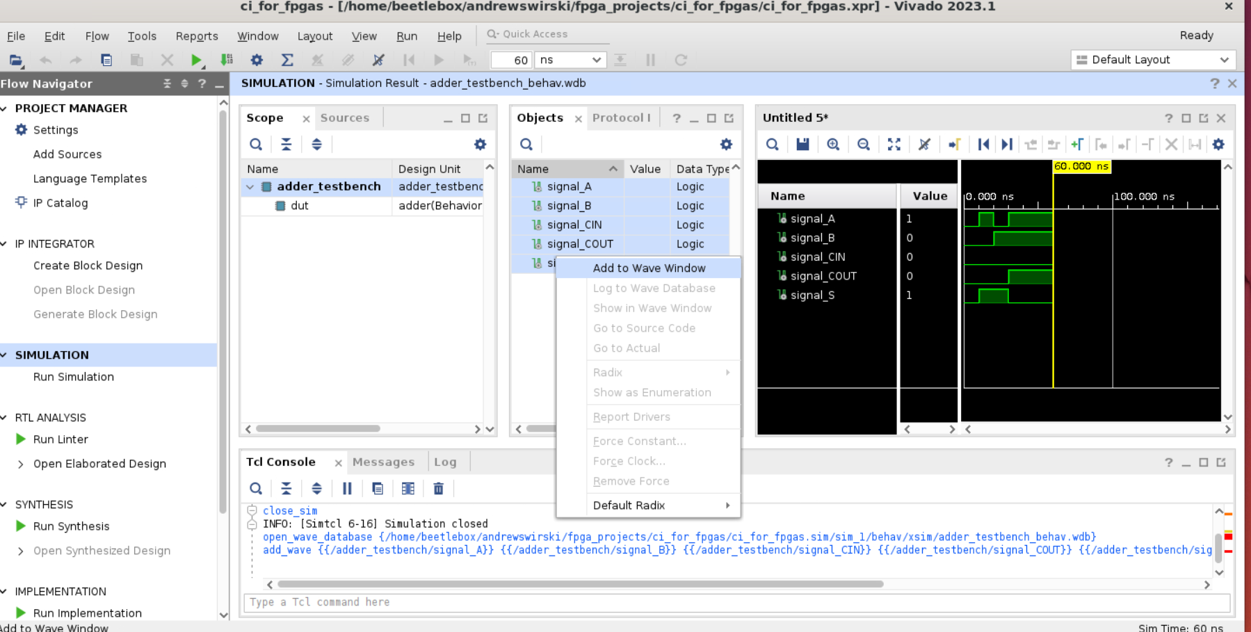
Conclusion
In this section, you have:
- Created a new Vivado project for an Arty A7-100.
- Created a basic full adder and a corresponding testbench.
- Set up a git repositoy and pushed the Vivado project to it.
- Created a tcl file to automatically run the project.
- Linked the repo with BeetleboxCI and ran the tcl file.
- Learned how to parse the generated report for assertion errors.
- Downloaded waveforms and displayed them using the Vivado GUI.
In the next section, you will learn how to synthesize the hardware and run tests on your FPGA device.